Actual Valve Timing Diagram of I.C. Engine:
In Theoretical valve Timing Diagram the inlet and exhaust valve open and close at Dead Centers.but in Actual valve timing Diagram the inlet and exhaust valve doesn't open and close at Dead Centers.
Valve Timing Of Four-Stroke Petrol /Spark Ignition Engine( SI Engine):


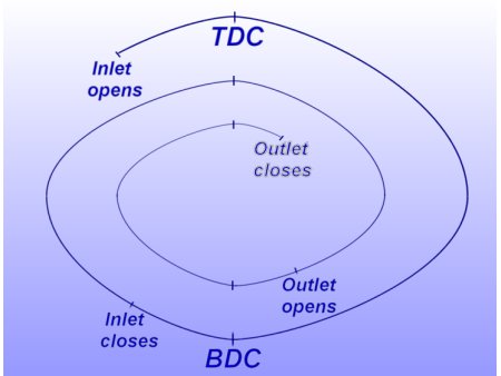
- In The valve timing diagram, the inlet valve opens before the piston reaches TDC or in other words, while the piston is still moving up before the beginning of the suction stroke.
- Now the piston reaches the TDC and the suction stroke starts. The piston reaches the BDC and then starts moving up. The inlet valve closes, when the crank has moved a little beyond the BDC This is done as the incoming charge continues to flow into the cylinder although the piston is moving upwards from BDC Now the charge is compressed (with both valves closed) and then and temperature) push the piston downwards with full force and the expansion or working stroke takes place.
- Now the exhaust valve opens before the piston again reaches BDC and the burnt gases start leaving the engine cylinder. Now the piston reaches BDC and then starts moving up, thus performing the exhaust stroke.
- The inlet valve opens before the piston reaches TDC to start suction stroke. This is done as the fresh incoming charge helps in pushing out the burnt gases.
- Now the piston again reaches TDC, and the suction stroke starts. The exit valve closes after the crank has moved a little beyond the TDC.
Valve Timing Diagram For A Four Stroke Cycle Diesel Engine :
- In the valve timing diagram the inlet valve opens before the piston reaches TDC. the piston is moving up before the beginning of the suction stroke.
- Now the piston reaches the TDC and the suction stroke starts. The piston reaches the BDC and then starts moving up. The inlet valve closes, when the crank moves BDC.

- This is done as the incoming air continues to flow into the cylinder although the piston is moving upwards from BDC.
- Now the air is compressed with both valves closed. The fuel valve opens a little before the piston reaches the TDC. the fuel is injected in the form of very fine spray, into the engine cylinder, which gets ignited due to the high temperature of the compressed air. The fuel valve closes after the piston has come down a little from the TDC. The fuel is injected into the engine cylinder. The burnt gases push the piston downwards, and the expansion or working stroke takes place.
- Now the exhaust valve opens before the piston again reaches BDC and the burnt gases start leaving the engine cylinder.
- Now the piston reaches BDC and then starts moving up thus performing the exhaust stroke. The inlet valve opens before the piston reaches TDC to start suction stroke. This is done as the fresh air helps in pushing out the burnt gases.
- Now the piston again reaches TDC, and the suction starts. The exhaust valve closes when the crank has moved a little beyond the TDC. This is done as the burnt gases continue to leave the engine cylinder although the piston is moving downwards.
Valve timing Diagram For Two Stroke Petrol SI Engine( Port Timing Diagram For SI Engine):

- In the valve timing diagram, as shown we see that the expansion of the charge starts as the piston moves from TDC towards BDC.
- First of all, the exhaust port opens a fraction of the crank revolution, the transfer port also opens and the fresh fuel-air mixture enters into the engine cylinder. This is done as the fresh incoming charge helps in pushing out the burnt gases.
- Now the piston reaches BDC and then starts moving upwards. As the crank moves a little beyond BDC, first the transfer port closes and then the exhaust port also closes. This is done to suck fresh charge through the transfer port and to exhaust the burnt gases through the exhaust port simultaneously.
- Now the charge is compressed with both ports closed and then ignited with the help of a spark plug before the end of the compression stroke. This is done as the charge requires some time to ignite. By the time the piston reaches TDC, the burnt gases (under high pressure and temperature) push the piston downwards with full force, and the expansion of the burnt gases takes place.
- It may be noted that the exhaust and transfer ports open and close at equal angles on either side of the BDC position.
Valve Timing Diagram For A Two-Stroke Diesel Engine( Port Timing Diagram For CI Engine:

- In the valve timing diagram, the expansion of the charge (after ignition) starts as the piston moves from TDC towards BDC. First of all, the exhaust port opens before the piston reaches BDC and the burnt gases start leaving the cylinder. After a small fraction of the crank revolution, the transfer port also opens and the fresh air enters into the engine cylinder. This is done as the fresh incoming air helps in pushing out the burnt gases.
- Now the piston reaches BDC and then starts moving upwards. As the crank moves a little beyond BDC, first the transfer port closes and then the exhaust port also closes. This is done to suck fresh air through the transfer port and to exhaust the burnt gases through the exhaust port simultaneously.
- Now the charge is compressed with both the ports closed. The fuel valve opens a little before the piston reaches the TDC.
- Now the fuel is injected in the form of very fine spray into the engine cylinder, which gets ignited due to the high temperature of the compressed air. The fuel valve closes after the piston has come down a little from the TDC. ‘This is done as the required quantity of fuel is injected into the engine cylinder.
- Now the burnt gases (under high pressure and temperature) push the piston downwards with full force and expansion of the gases takes place. It may be noted that in a two-stroke cycle diesel engine, like a two-stroke petrol engine, the exhaust and transfer ports open and close at equal angles on either side of the BDC position.
Comments