
NX CAD Design....


Theoretical valve timing diagram of I.C. Engine

Theoretical valve timing diagram :

 
Theoretical valve timing diagram is of two types-
  • For Four stroke cycle engine
  • For Two stroke cycle engine
 Theoretical valve timing diagram for four-stroke cycle engine:
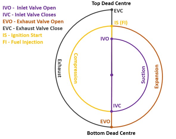
  • In The theoretical valve timing diagram for a four-stroke cycle engine, a Piston moves from TDC (Top dead center) to BDC (Bottom dead center). the inlet valve opens and closed during movement of crankshaft. 
  • In this diagram,the piston moves from TDC to BDC, the inlet valve opens at IVO and the suction process takes place from IVO(inlet valve open) to IVC(inlet valve closed).
  • The crankshaft revolves through 180º and the piston moves from BDC to TDC. the inlet valve and exhaust valve both are close and the compression takes place from IVC (inlet valve close) to IS (Ignition start).
  • The crankshaft revolves through 180º and the piston moves from TDC to BDC At IS, the fuel is fired and the expansion takes place from IS to EVO (Exhaust valve open).
  • The crankshaft revolves through 180º and the piston again moves from TDC to BDC. At EVO, the exhaust valve opens and the exhaust takes place from EVO (Exhaust valve open) to EVC (Exhaust valve close) The crankshaft again revolves through 180º and the piston moves back to TDC.
What is Valve Timing diagram in Four-stroke Engines? - ExtruDesign


Theoretical valve timing diagram for the Two-stroke cycle engine:
  • In The theoretical valve timing diagram for a Two-stroke cycle engine, a Piston moves from TDC (Top dead center) to BDC (Bottom dead center). the inlet valve opens and closed during movement of crankshaft. 
  •  In this diagram, the fuel is fired at A and the expansion of gases takes place from A to B.
  • The crankshaft revolves through approximately 120º and the piston moves from TDC to BDC. At B, the valves open, and suction, as well as exhaust, take place from B to C.
  • The crankshaft revolves through approximately 120º and the piston moves first to BDC and then little upwards. At C. both the valves close and compression takes place from C to A. The crankshaft revolves through approximately 120º and the piston moves to TDC.
Theoretical valve timing diagram for two-stroke cycle engine


Comments

Popular posts from this blog

NX CAD Design....


WORKSHOP : Precautions || workshop || Safety

  What safety precautions should be observed while working in the workshop ? 1) Keep shop floor clean, free from oil and other slippery materials. 2) Wear proper dress and avoid loose clothing and loose hair. 3) Wear shoes and avoid chapels. 4) Avoid playing, loose talk and funning inside the shop floor. 5) Keep good housekeeping and put all unnecessary items and rejected items in scrap box. 6) Learn everything about the machine before starting and clear all the doubts. 7) Keep a safe distance from rotating and sliding parts. 8) Never store inflammable materials inside or around the shop. 9) Never play with electricity, fire, parts with sharp edge etc. 10) Keep fire buckets and extinguishers ready for use.  

What is the MAGNETO IGNITION SYSTEM? | WORKING | knowledgeaboutautomobile957

MAGNETO IGNITION SYSTEM Magneto is a special type of ignition system with its own electric generator to provide the necessary energy for the system. It is mounted on the engine and replaces all the components of the coil ignition system except the spark plug. A magneto when rotated by the engine is capable of producing a very high voltage and it does not need a battery as a source of external energy. The high tension magneto incorporates the windings to generate the primary voltage as well as to step up the voltage and thus does not require a separate coil to boost up the voltage required to operate the spark plug. Magneto can be either rotating armature type or rotating magnet type. In the first type, the armature consisting of the primary and secondary windings all rotate between the poles of a stationary magnet. whilst, in the second type the magnet revolves and the windings are kept stationary. A third type of magnet to called the polar inductor type is also in use. In the polar in...